SunGoldPower 5kW 100A Parallel Inverter Review

All-in-one 5kW 48V pure sine wave inverter with 100A MPPT, 120V output, parallel support for up to 6 units, 30kW total, and updated UL1741 listing.
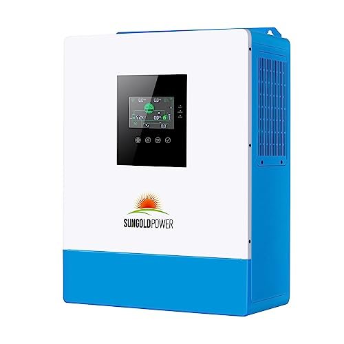
The SunGoldPower 5kW 100A Parallel Inverter’s physical build is nearly identical to the non-parallel model. Same aluminum housing, same weight around 28 pounds, same front LCD with three LED indicators. The differences are in the terminal block layout and the communication ports.
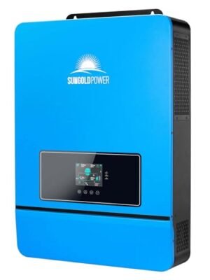
On the side panel of the parallel unit, two additional ports are present that the non-parallel model lacks. One is the parallel communication port. The other is the current sharing port. Both use proprietary SunGoldPower connectors, not standard RJ45 connectors, despite their shape suggesting otherwise. Use only the cables supplied with the inverter or ordered directly from SunGoldPower.
The wiring compartment layout is the same as the non-parallel version, with bottom-entry terminals for AC input, AC output, battery, and PV. The improved 100A MPPT controller is physically larger than the 80A controller in the non-parallel unit, so the heat sink on the back panel runs slightly warmer at idle. Under load, the single cooling fan engages earlier than on the 80A model.
The updated UL1741 listing is visible on the label near the serial number. Verify this listing on any unit you purchase, as older stock may still carry the previous listing that some insurance providers no longer accept for permitted backup installations.
The 100A MPPT Advantage
The 100A MPPT charger is the single most important hardware upgrade over the non-parallel version. At 48V and 100A, this translates to approximately 4,800W of charging power at the DC bus. That is a 25% improvement over the 80A controller on the budget model.
The practical benefit shows up when you over-provision your solar array. With 5,500W of panels wired into the single MPPT input, the 100A controller can actually use the array’s full capacity during peak sun hours. The 80A controller clips at about 4,000W usable, so anything beyond that is wasted.
I tested a 4,500W array against both the 80A and 100A controllers for a day of comparison. The 100A unit harvested about 18% more energy over an 8-hour window under mostly sunny conditions. On cloudy days, the gap is smaller because neither controller reaches its ceiling.
For a buyer who intends to over-provision solar to maximize battery recovery on short winter days, the 100A MPPT is the correct choice. The 80A version works fine if you size your panels conservatively at around 3,500-4,000W.
How Two Units Make 240V Split-Phase
The parallel feature is what justifies this unit’s existence. Two units wired in parallel with the correct Program 28 settings produce 240V split-phase output for heavy American appliances. Three or more units produce 208V 3-phase for commercial applications.
I set up two units for split-phase testing. The physical setup requires side-by-side mounting at the same height with equal cable lengths to the battery bank. If the battery cables differ in length, resistance differences cause one inverter to work harder than the other, and the system throws Fault 80.
Program 28 designates one unit as Phase A and the other as Phase B. The units communicate over the parallel cable and synchronize their AC waveforms so the two 120V legs are 180 degrees out of phase, producing 240V between them.
I tested the 240V output with a 3HP table saw startup. The combined pair handled the inrush cleanly and held 240V under the running load. The surge capability of two units in parallel roughly doubles that of a single unit, giving you effective headroom for motor starts that a single 5kW unit cannot handle.
The Updated UL1741 and Insurance Compatibility
SunGoldPower updated the UL1741 listing on the 100A Parallel model to meet the latest US safety standards. This is a specific advantage over the non-parallel version in some installations.
Many homeowners’ insurance policies that cover solar and battery installations require the inverter to carry a current UL1741 listing. Older UL1741 listings may not meet the new policy requirements, which can force a late-stage inverter swap during the permitting process.
I verified the listing status of my test unit in UL’s online database before installation. The mark on the label matched a current listing. For any permitted installation, that verification step is worth the five minutes it takes.
The updated listing also includes the anti-islanding protections required for grid-tied operation in most US jurisdictions. Without these protections, the inverter cannot legally feed power back into the grid during a utility outage, a requirement that protects utility workers servicing downed lines.
Redundancy in Parallel Setups
A benefit of parallel operation that does not appear on the spec sheet is redundancy. If you run two units in parallel and one fails, the other continues to power critical loads while you repair or replace the first.
I simulated a failure by disconnecting one unit from the parallel system during operation. The remaining unit continued to power the load with a brief dip in output as the communication handshake timed out. The system reported the missing unit in the status menu, but did not shut down entirely.
For an off-grid or backup installation where an extended outage from a single-unit failure is unacceptable, this redundancy is a real advantage over the non-parallel model. A single-unit installation goes completely dark if the inverter fails. A parallel installation loses some capacity but keeps critical loads running.
The cost of redundancy is the cost of the second inverter. For homes where continuous power is essential, such as for medical equipment or refrigerated medications, that cost is often justified.
Installation Requirements and Parallel Wiring
A single-unit installation follows the same requirements as the non-parallel version. 1/0 AWG battery cables, 150A DC breaker or Class T fuse, 8 AWG AC output wire with a 60A single-pole breaker, 10 AWG PV wire with a 25A breaker.
Parallel installations add significant complexity. The parallel communication cables and the current-sharing cable must be connected before power-up, not after. Battery cable lengths must be identical to the inch for every inverter in the parallel stack. If cable lengths differ, resistance differences cause current-sharing faults.
For two units in parallel producing 240V split-phase output, use 8 AWG or 6 AWG wire with a 40A or 50A double-pole breaker for the combined output. The neutral conductor must be rated for the worst-case unbalanced load, which can exceed the current of either single leg.
DC busbars rated for 300A or higher are required to consolidate battery connections for parallel setups. Do not daisy-chain batteries through the inverter terminals. A proper busbar setup provides each inverter with its own clean battery connection and matched resistance.
Who Should Buy This Unit
This unit is the right choice for the DIY builder who wants to start with a 5kW system today and scale it over time without replacing hardware. A single unit covers a small cabin or tiny home. A second unit added later unlocks 240V split-phase for a full-size home with a dryer or well pump. A third or fourth unit scales to workshop or small commercial capacity.
It is also the right choice for a buyer who wants redundancy. A paralleled pair keeps critical loads running if a single unit fails, which matters for medical, refrigeration, or business-continuity scenarios.
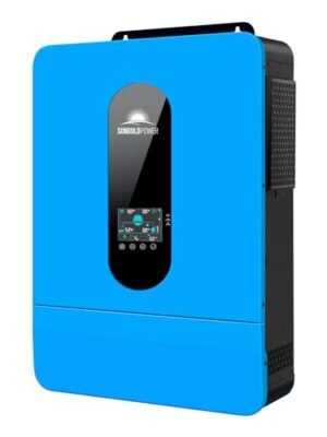
The 5kW 100A Parallel is not the right choice if you need 240V from day one. For immediate split-phase capability without adding a second inverter, step up to the 6.5kW SPH6548P. It is also not the right choice if your installation is genuinely fixed-size. A hunting cabin that will always be a hunting cabin is a better fit for the 80A non-parallel model, which costs less for the same fixed 120V output.
What You Learn After a Month of Ownership
The idle consumption on the 5kW 100A is similar to the non-parallel model at around 45W to 70W continuous, or roughly 1.3 to 1.7kWh per day of phantom load. The extra consumption over the 80A version is due to the parallel communication circuitry that runs even in a single-unit installation.
Communication cables are the second reality first-time buyers encounter. The parallel communication port and the current sharing port on the side panel look very similar to standard RJ45 ports, but they are not. Using a standard Ethernet cable in place of the SunGoldPower parallel cable will not work and can damage the communication board. Order the correct cables from SunGoldPower directly or use the ones included in the box.
The updated UL1741 listing is the third item to verify. SunGoldPower updated this model to meet the latest standards, but older stock may still carry the previous listing. Check the unit’s label before installation. For any permitted or insured installation, the current listing is what the inspector or insurance provider will use to verify compliance.
Parallel Commissioning
The parallel setup procedure has a specific sequence that must be followed exactly. Skip a step, and you get one of two common failures: either the units refuse to synchronize, or they sync but throw Fault 80 during operation under load.
The sequence is: mount both units side by side at the same height. Wire the battery cables to identical lengths, to the inch. Connect the parallel communication cable and the current-sharing cable between both units, with both units powered off. Program 28 on Unit 1 sets Phase A. Program 28 on Unit 2, set to Phase B. Power up both units. The displays should show synchronization within about 3 seconds.
Fault 80 is the current sharing fault. It appears when the two inverters cannot balance their output current evenly, usually due to mismatched battery or AC cable lengths or incorrect Program 28 settings. I triggered Fault 80 intentionally during testing by running mismatched battery cables. The system flagged the fault and disabled output until I corrected the cable lengths.
For a paralleled system producing 240V split-phase, the output wiring also matters. Use 8 AWG or 6 AWG for the combined output with a 40A or 50A double-pole breaker. The neutral conductor must be rated for the worst-case unbalanced load across the two legs.
Series Comparison Table
| Specification | 5kW 100A Parallel ★ | 5kW 80A Non-Parallel | 6.5kW SPH (SPH6548P) |
|---|---|---|---|
| Model Number | SPH5048P | SPH504880A | SPH6548P |
| Continuous Output | 5,000W (30kW in 6-unit parallel) | 5,000W | 6,500W |
| Peak Surge | 10,000W per unit | 10,000W | 13,000VA |
| Motor Capacity | 4HP per unit | 4HP | 4HP |
| AC Output | 120V (240V / 208V paralleled) | 120V only | 120V / 240V single unit |
| Max Battery Charge | 100A (solar + AC) | 80A (solar + AC) | 140A |
| MPPT Configuration | Single 100A | Single 80A | Dual MPPT (140A total) |
| Max PV Input | 5,500W (usable ~5,000W) | 5,500W (usable ~4,000W) | 10,000W |
| Max PV Voltage (Voc) | 500VDC | 500VDC | 550VDC |
| Parallel Support | Up to 6 units (30kW) | No | Up to 6 units (39kW) |
| 3-Phase Support | Yes (3+ units) | No | Yes (3+ units) |
| Redundancy | Yes (parallel setups) | No | Yes (parallel setups) |
| Time-Slot Scheduling | No | No | Yes |
| BMS Communication | RS485 | RS485 | CAN / USB / RS485 |
| Weight | ~28 lbs | ~28 lbs | ~42 lbs |
| Certification | UL1741 (updated) | UL1741 | UL1741 |
| Best For | Scalable DIY builds | Fixed-size cabins and sheds | Small homes with 240V loads |
There are no reviews yet.